
Connectivity infrastructure solution
Fibre Optics
Fibre links that carry connectivity between buildings, gates and distant equipment positions where copper cabling cannot reasonably reach.
What the system is for
Copper cabling cannot reach distant gates, perimeters or separate buildings reliably.
Fibre is used where distance is the problem. It is infrastructure rather than a security device — it connects the systems you already have across a large or split site.
- Links between separate buildings, gatehouses or perimeter positions
- A backbone that distant cameras, switches and access devices connect back to
- Conversion to Ethernet at each end so existing equipment can be used
- Terminated, patched connections rather than improvised joints
- A route that can be maintained and extended later
Typical premises
- Industrial facilities
- Institutions
- Estates
- Commercial buildings
What a fibre installation usually includes
A fibre link is a route, two ends and the equipment that connects it to the rest of the network. The specification of each is set once the route is walked.
Fibre route
The physical path between positions — buried, catenary or in containment, depending on the site.
Termination and patching
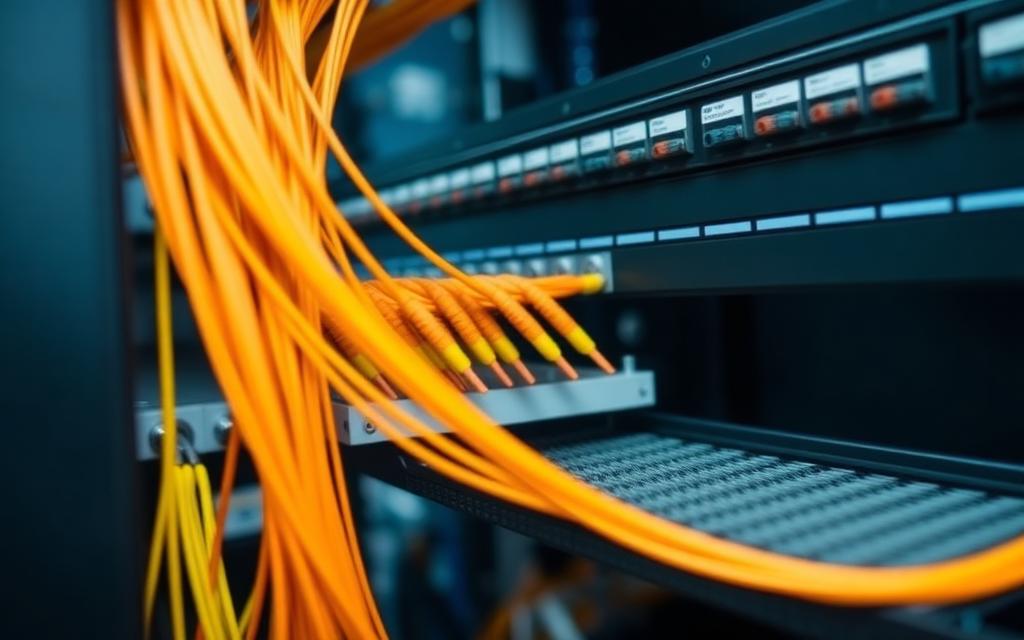
Panels and terminated connections so each end is accessible and testable.
Media conversion
Converting the fibre link to Ethernet where equipment at either end needs it.
Switching at each end
The switches that connect cameras, terminals and computers to the link.
Power and protection
Supply and enclosure arrangements at the equipment positions along the route.
Fibre type, core count, connector type and achievable distance are determined by the route survey and the equipment at each end — we confirm them per project rather than in advance.
System design considerations
Link distance
How far apart the endpoints sit is the first thing to establish; it drives the whole specification.
Route survey
Walking the actual path shows the obstacles — roads, drainage, boundaries — that a drawing hides.
Pathway and protection
Buried, catenary or in containment: the route has to survive traffic, weather and future ground works.
Endpoint positions
Each end needs a secure, ventilated position with power and space for termination equipment.
Termination and patching
Terminated, panelled ends make faults findable and future changes straightforward.
Integration with existing network
The link has to meet the switching and cameras already on site, so it is designed with them in mind.
Testing
Links are tested after termination so the connection is proven before systems are moved onto it.
Maintenance access
Access points and slack are planned so a future repair does not mean redoing the route.
Expansion
Allowing capacity beyond today's requirement avoids repeating civil work for the next building.
How a project runs
- 01Discussion of the buildings, distances and systems to be linked
- 02Route survey and endpoint assessment
- 03Design of the link, terminations and conversion points
- 04Written quotation
- 05Route preparation, cable installation and containment
- 06Termination, patching and testing
- 07Handover with route and endpoint documentation
- 08Maintenance and fault attendance
Related services
- Site SurveysOn-site assessment to determine coverage, equipment and cabling routes.
- System DesignDesigning systems that match the site, budget and required outcome.
- MaintenanceScheduled checks that keep systems recording, detecting and reporting.
- TroubleshootingDiagnosing faults on existing systems, including systems we did not install.
- NetworkingNetwork infrastructure that keeps security systems online.
Next step
Linking buildings across a site?
Tell us where the endpoints are and what must connect. We will advise on the route, termination and equipment, and prepare a quotation.